Rake Kit Installation
Honda GL1800, F6B
Download PDF Version
Tools Required
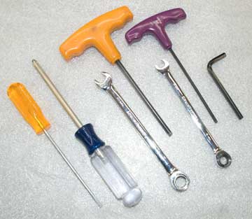
- • Small stanard screwdriver
- • #2 Phillips or JIS screwdriver
- • 10mm end-wrench or ratchet and socket
- • 8mm end-wrench or ratchet and socket
- • 3mm hex wrench
- • 5mm hex wrench
Parts Included

- 1 - Right Fixed Bracket (attach to male rail)
- 1 - Left Fixed Bracket (attach to male rail)
- 2 - Swing Brackets (attach to top shield)
- 2 - Adjustment Arms
- 6 - 6mm x 10mm SS cap screws
- 2 - 6mm SS Nylock nuts
- 4 - 6mm SS flat washers
- 4 - 6mm SS lock washers
- 4 - 5mm x 16mm SS button-head screws
- 4 - 5mm SS Nylock nuts
- 4 - #12 x 1/2” SS pan head screws
- 4 - Snap-Cap sets
Stainless steel parts are shipped bare. They can be painted, powder coated or polished to taste.
Installation Instuctions
- Remove your Top Shield and place it on a soft surface.
- Remove the Male Rails from the Top Shield by first removing the four snap-caps with a small standard screwdriver. Then, remove the four mounting screws. Set aside the hardware and Trim Pieces. You will use the Trim Pieces again shortly.
- Mount the Fixed Brackets to the Male Rails with the slide and pivot tabs to the outside and the slide tab towards the top (rounded end) of the rail. Use the #10 x 1/2” SS pan head screws supplied in the kit. If you don't use the snap caps you may have to trim these screws for proper clearance between the rails. Center the Fixed Bracket on each male rail with the brackets at equal vertical locations on the rails. Do not over tighten the #10. You may install the black snap caps at this time.
- Attach Swing Brackets to the Fixed Brackets at the pivot tabs with 6mmx10mm cap screws and lock-nut. Swing Brackets are identical. With the Swing Bracket tab located inside of the Fixed Bracket tab. The mounting surfaces of each bracket set should be parallel The pivot attachment should only be snug: allow the Swing Bracket to pivot on the Fixed Bracket with minimal resistance. You may need to slightly bend the pivot tabs so that the top tab on the Swing Bracket and the slide tab on the Fixed Bracket are flush.
- Attach the Adjustment Arms inside of the top tabs on the Swing Brackets and inside the slide tab on the Fixed Bracket using 6mm x 10mm cap screws, lock washers and flat washers. Do not tighten these, yet.
- Mount the Swing Brackets to the Top Shield with 5mmx16mm button-head machine screws, snap cap bases, and lock-nuts. Insert the screws through the snap cap bases, then through the Trim Pieces you removed earlier through the Top Shield, then through the Swing Bracket. Attach the nuts and leave them loose enough that the brackets can slide easily on the Top Shield. Additional vertical adjustment is available in the Swing Bracket for positioning the top shield as desired. (Extra Trim Pieces are included in kits for use with the electric option. Place those between the Shield and Swing Bracket.)
- Before you proceed, you may want to protect the windshield garnish. The Top Shield will be loose and could slide into the paint.
- Reinstall the Top Shield. Lock the Top Shield in lowest position. Set the top shield height in the Swing Brackets as desired. If you have the electric option installed, align the top actuator mount with the top of the actuator in its lowest position.
- Raise the arms in the slide tabs top put the Top Shield is in the most vertical position and tighten one 6mm cap screw in each bracket. Square up everything and align the rails at equal height on the Top Shield. Give the Top Shield a little giggle to make sure all the pieces are lined up and can move freely. You may want to make some measurements to assure everything is square. Tighten the four 5mm mounting screws and nuts.
- The Top Shield should slide smoothly and you can start playing with your Top Shield angle by loosening the cap screws in the adjustment arms. When you are satisfied with the angle, you can tighten the pivot attachment.
- Please call if you have any problems.
Enjoy your Ride!!!
Don’t forget to check your speedometer.
Electric Option Supplement
Download PDF Version
Parts Included
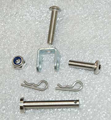
- 1 - M4 x 30mm Clevis Pin
- 2 - R-Type Cotter Pins (one spare)
- 2 - 4mm Pivots
- 1 - M4 x 20mm button head screw
- 3 - M4 x 16mm button head screw
- 1 - M4 acorn nut
- 4 - M4 Nylock nut
Optional Parts Included
- 2 - Black ABS trim pieces
- 4 - M5 x 20mm button head screws
Actuator Modifications and Installation
- Remove the lower actuator mounting screw and lead-wire stress-relief.
- Actuator Modifications are different depending on which actuator you have.
- Type 1 Actuator
(square motor case – sold through early 2017) - Option 1
- A. Do nothing. Install pivots on both ends of the actuator.
- Option 2
- A. Install with a pivot on the lower mount only.
- B. Firmly holding the actuator motor case and piston shroud, turn the black clevis on top of the piston 90° counterclockwise (unscrew it). Use a clevis pin or 4mm screw for leverage if necessary. The whole piston may rotate, this is okay. You can remove the piston completely, rotate the clevis, then reinstall the piston.
- C. Slightly ovalize the hole in the top clevis to accommodate the new shield angle. Use a needle file or appropriate size drill bit being careful not to remove much material from the top of the clevis.
- Type 2 Actuator
(oval motor case – current version) - A. Drill a 4mm hole in the lower clevis of the actuator case perpendicular to the existing hole.
- B. Sand or file the clevis sides so that a pivot will fit over the new hole.
- C. Mount one pivot to the Windbender Base Unit with an M4 x 16mm screw using the nylon shoulder washer, flat washer and lock-nut that come with the Electric Option kit. The pivot should be only tight enough to not rattle.
- Type 1 Actuator
- Mount the actuator and stress relief to the to the pivot on the base shield with an M4 x 20mm screw. You may use a 16mm screw if you don’t use the stress relief. Tighten the assemble so that the actuator can still move in the pivot with minimal friction.
- Check clearance between the Top Shield and actuator. If needed, install a black trim piece between the Top Shield and each Rake Kit bracket using M5 x 20mm screws and snap caps.
- Tighten the stress relief around the actuator lead wires or zip-tie the lead wires to the piston housing.
- Actuator top mount:
- Type 2 Actuator and Type 1 Actuator-Option 1
- A. Install a pivot on the Hollow Bolt in the Top Shield with the 25mm screw, nylon washers and cap-nut. Use medium strength thread locker and tighten so the pivot doesn't rattle but can be rotated by hand.
- B. Attach the actuator top clevis to the pivot with the original clevis pin or 16mm screw and lock-nut.
- Type 1 Actuator Option 2
- A. Use new 4mm clevis pin with R-type cotter pin through the hollow bolt. Do Not attempt to use the original detent ball clevis-pin on the top actuator mount with a Rake Kit. The actuator will fall off and your flying Top Shield could cause damage, injury or worse!!